Lunar Sling Launcher - Release Mechanism
Building a subscale prototype. Part 1 - release mechanism
The previous two blog posts described what lunar sling tethers are and why they are a good idea.
But a lot has been written about the topic. Now it's time to build something.
Why?
A sling launcher on earth is pretty useless. You have some fundamental velocity limitations due to atmospheric drag.
A useful number is the rough energy retention constant of the system. The total energy in the system divided by the power loss.
If this becomes very small, on the order of seconds, a tether sling launcher where you slowly add energy is no longer viable. You would be better off with a system like a trebuchet which adds energy faster.
I did a quick back of the envelope calculation. At tip velocities above 100 m/s, the energy retention time would be in the single digit seconds. A sweet spot is 50 m/s, where the energy retention time is 30 to 60s, and you can still gradually add energy.
So the best you can do with sea level atmosphere is a sling launcher that launches stuff at 50 m/s. That is much slower than even medieval trebuchets.
So why build this at all?
First of all - building stuff is fun. I really enjoy playing with 3d printers, embedded systems and mechanical systems.
Second - I think you can learn a lot about the dynamics of a sling launcher by building a subscale prototype. Things like release mechanism, release dynamics and reel out process aren't fundamentally different.
Of course things are easier in a way because the air provides damping. But as we will see, the release is very violent even with air damping.
Where do we start?
In the initial post of this series I mentioned that you need about 10ms release timing precision for a good insertion to EML1, and just postulated that this is easy.
So let's see if it is really easy by building and testing a mechanism.
Release mechanism requirements
Briefly before release, the payload pulls with several gs. For our notional 1000kg 10km system, the force on the release mechanism is 600 000 N or 60 tons.
For a notional 10m, 50m/s subscale system we would have a tip g at release of 25.5. For a 1kg payload that would be a force of 250 N or 25kg.
We want to use a tiny and lightweight actuator for the release mechanism. Nevertheless we need the release timing to be precise to within sub 100ms, ideally 10ms.
Since the release mechanism is near the tip of a tether, it should be self-contained with its own power supply. We should be able to command it via a radio signal.
Last but not least: we are swinging a heavy payload around with some speed. Accidental release, while not really dangerous, could cause a lot of damage. So we want the release mechanism to be really robust against accidental release.
How to test?
We don't have the rest of the system yet, and in any case we want to test this in isolation first. So we just need to put the mechanism under a well defined force, then trigger the release mechanism.
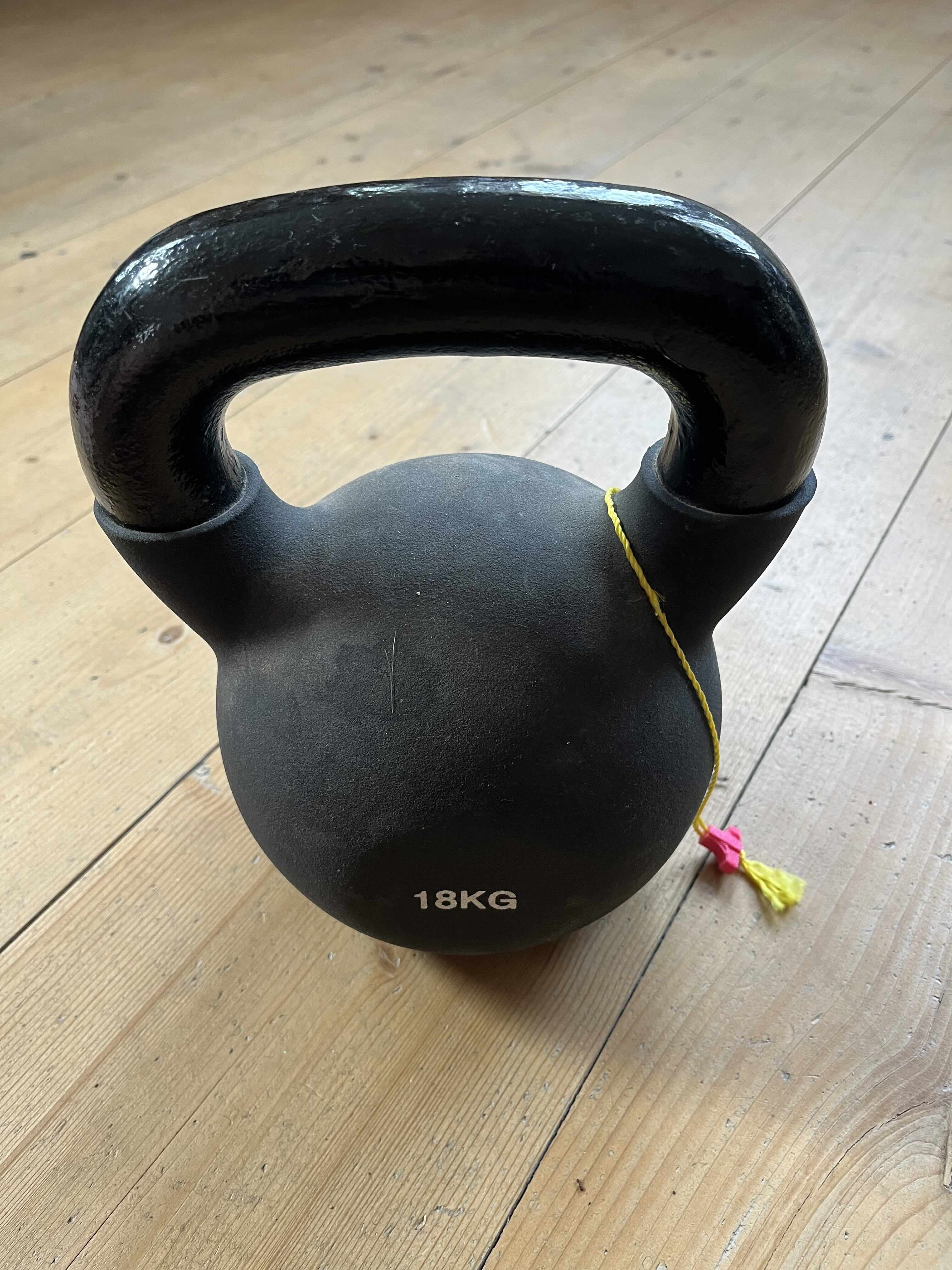
We could use some sort of exercise rubber band and tension it until we got the right force for our test, but the simplest approach is to just use a large mass, a kettlebell.
It is clear that we can't just use an actuator directly. We need a mechanism where a tiny and precisely timed force triggers the release. Then we need to make sure that the time for the ball rolling downhill is as deterministic as possible. We don't really care how long it takes, just that the duration is deterministic.

Ball bearings
We want everything to be as deterministic as possible. So we need to eliminate friction. Friction is notoriously nondeterministic, especially between rough 3d printed parts.
So we need ball bearings. I just bought a set of small ball bearings of various sizes on Amazon.
Note: Any 3d printed project is more fun if you have a small set of metal parts. Aluminium rods, springs and especially ball bearings.
Ball bearings also help reduce the force needed from the actuator to push the ball down the hill.
First attempt
My first attempt was to just design a hook that moves out of the way. The tether to the payload would either sit directly on the hook, or on a small latch.
We are going to drive this with a tiny servo which is unable to move the hook out of the way in a short time. So we use a rubber band, and have the actuator just trigger a mechanism that moves the hook.
Both the hook hinge and the hook itself contain ball bearings to make the "rolling down the hill" more deterministic.

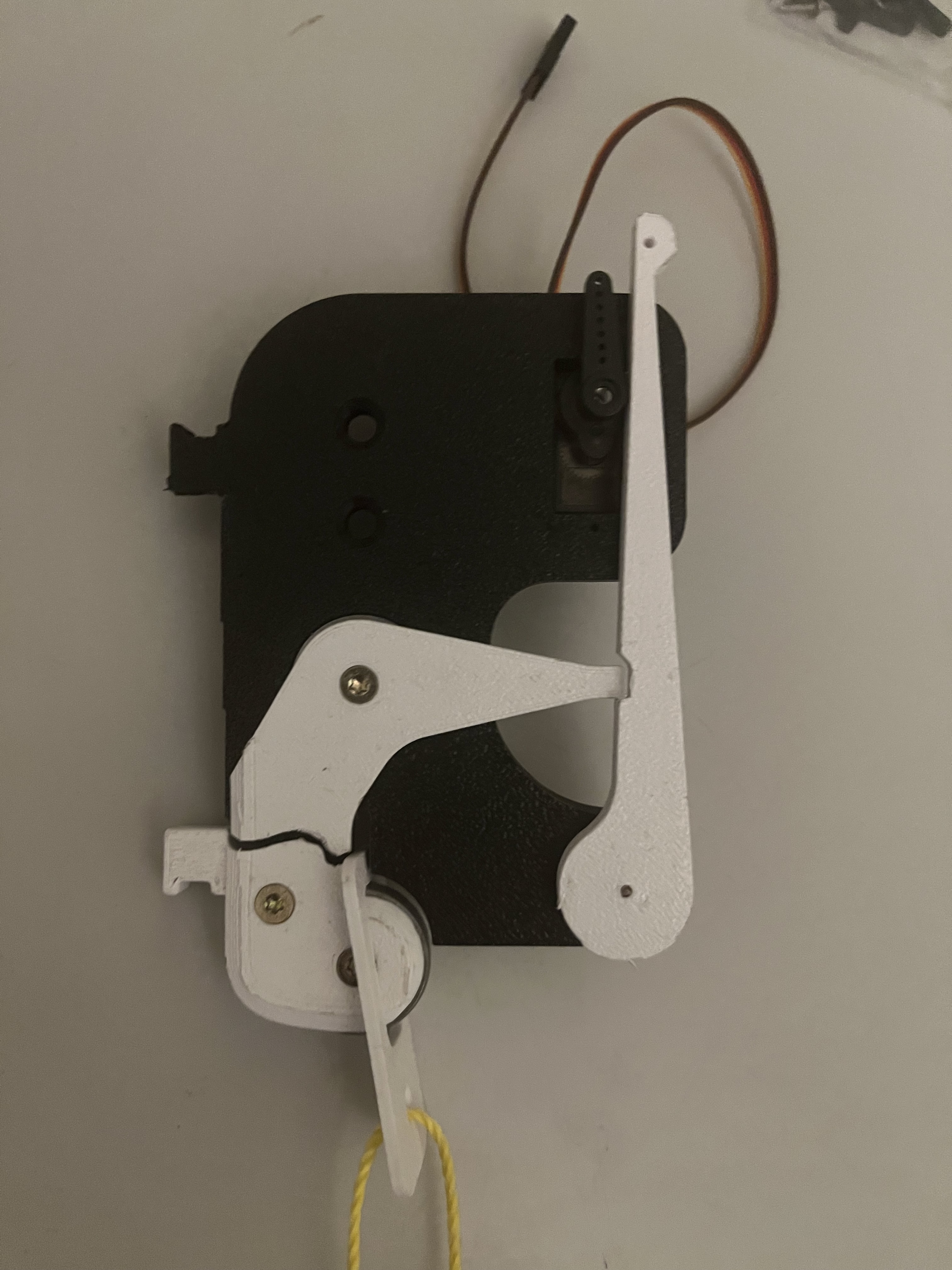
When I tried this out with the 18kg kettlebell, it did not work well with using just the rope. There is so much friction from the rope on the sides of the hook, so the rubber was not strong enough to open the hook at all.
Adding a small latch made it work, but after some attempts the hook broke.
I think this mechanism could be made to work well if you were to make the hook out of metal. But let's see if we can design something that also works reliably with cheap PLA parts.
Second attempt
The second attempt is more symmetric. The payload is attached to a hook that is clamped in by two arms. The arms can be made to quickly open using a rubber band. A small actuator triggers the opening.

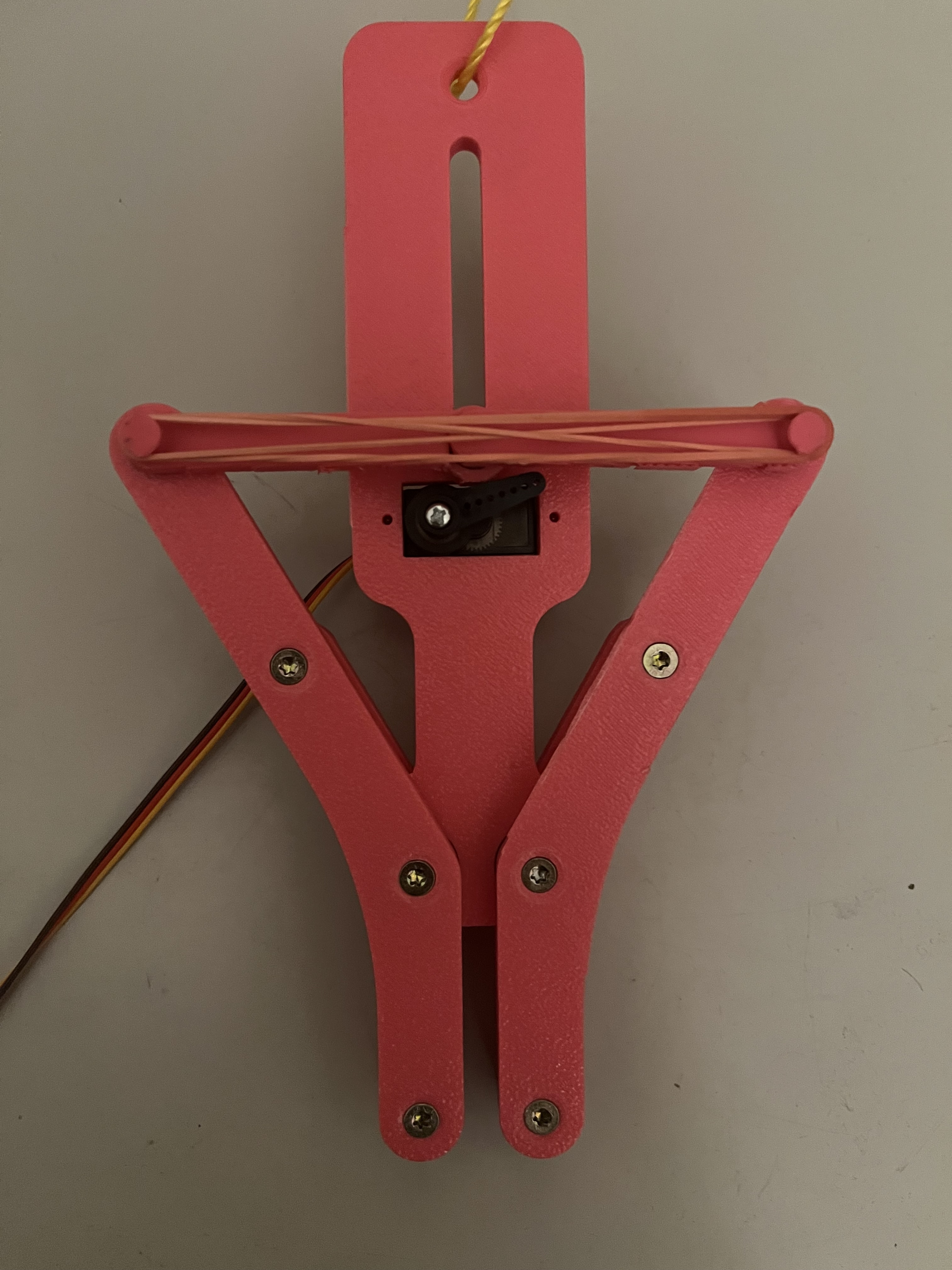
This mechanism is much better suited to low strength materials like PLA and works well when manually triggered. Just like the previous mechanism, it is safe from accidental release because the payload is completely enclosed before release.
How to trigger remotely
Eventually we want a fully self contained release mechanism that can be triggered remotely. For just a release trigger, we might be able to come up with something analog. But eventually we want to implement soft release with complex release timing. So let's just get a cheap embedded computer that can work with a tiny 5V power source.
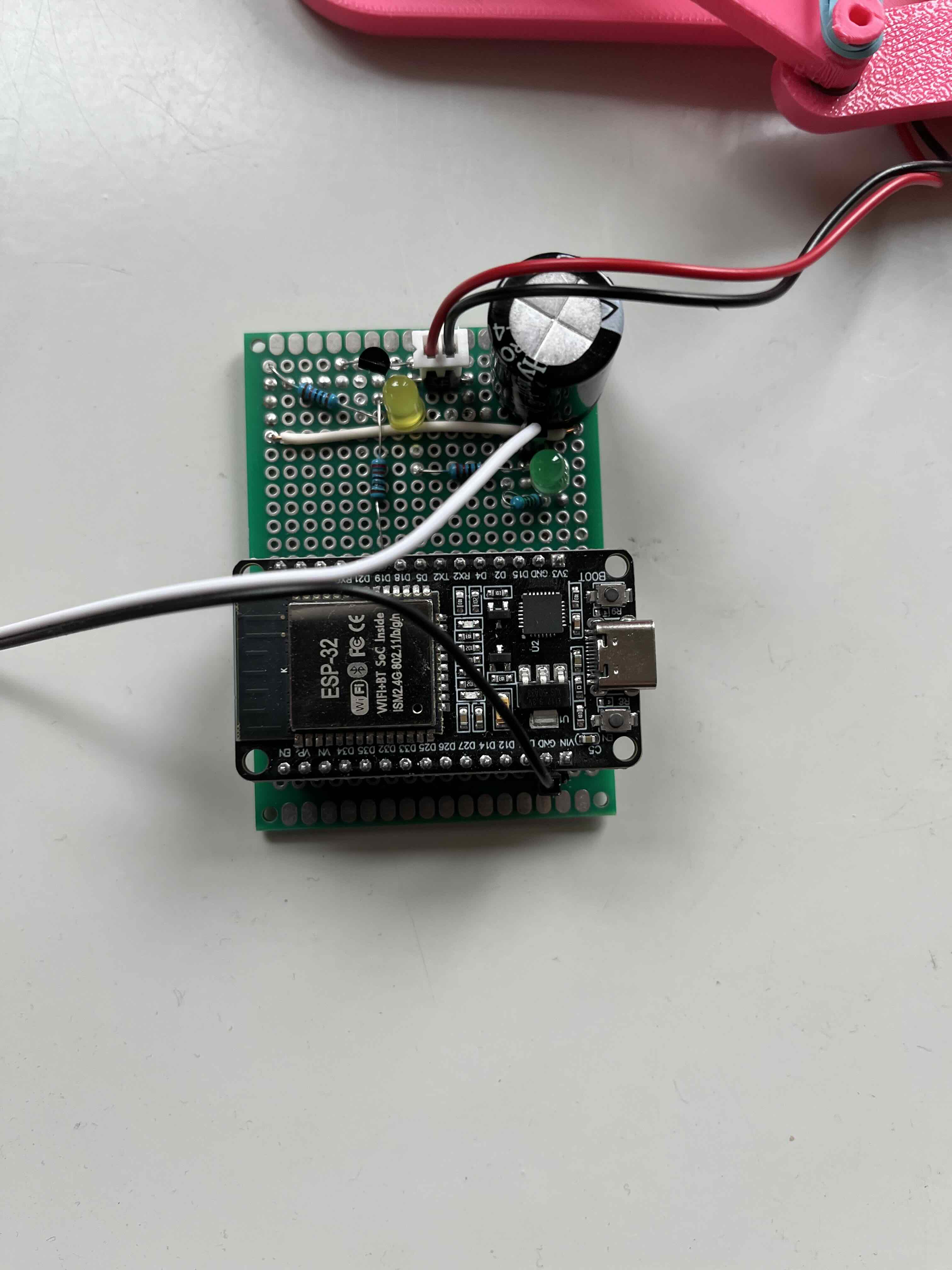
I got myself an Espressif ESP32 development kit that includes the embedded computer and a large set of sensors and actuators. The ESP32 supports both WiFi and Bluetooth, so it will be easy to implement remote control. It also has a large number of GPIO ports which can directly drive a model servo (a cheap one even comes with the dev kit).
Triggering via BLE
Initially I tested the triggering with an ESP32 connected via USB, but getting Bluetooth to work was surprisingly easy. LLM coding assistants really help navigating the maze of small issues that make getting embedded systems to work annoying.
The code is available on GitHub.
Measuring the release delay and determinism
To measure delay and determinism, I wired an LED to another GPIO port. As soon as we command the servo to rotate, we also switch the LED on. All we need to do then is to film the release mechanism in slow motion and measure the delay between the LED turning on and the mechanism triggering.
This does not measure the delay caused by BLE, but it will have to do for now. Once we have the integrated system working we can just launch a few payloads and measure the trajectory spread.
The weight is fully suspended by the tether, but just 10mm high. As you can see the release is pretty violent because the stored energy in the tether gets released. It's basically a catapult for the lightweight release mechanism.
This is using bad nylon rope I had lying around. Spectra would stretch less and thus contain less energy, but of course for a full scale system the total amount would still be significant.
Servos vs. solenoids vs. voice coil actuators
Servos are not really optimized to be extremely fast. They have a complex internal mechanism: an electric motor and a large reduction gear with a lot of backlash. So unsurprisingly there is a delay between the command and the first movement of the servo.
On the plus side, servos produce a lot of power directly from the 5V available via USB-C or the ESP32 power supply.
There are actuators that are more direct and therefore should have less delay and be more deterministic. The simplest direct linear actuator is a solenoid, just a coil with a ferromagnetic core.
Solenoids are also widely available for electronic locks, but need a slightly higher voltage, which creates some inconvenience.
At the top end in terms of directness are so-called voice coil actuators. Basically also solenoids, but without a ferrite core, often using a rare earth permanent magnet instead. These can be made almost arbitrarily fast and direct by customizing the coil. But let's first see if we can reach our goals with a simple solenoid.
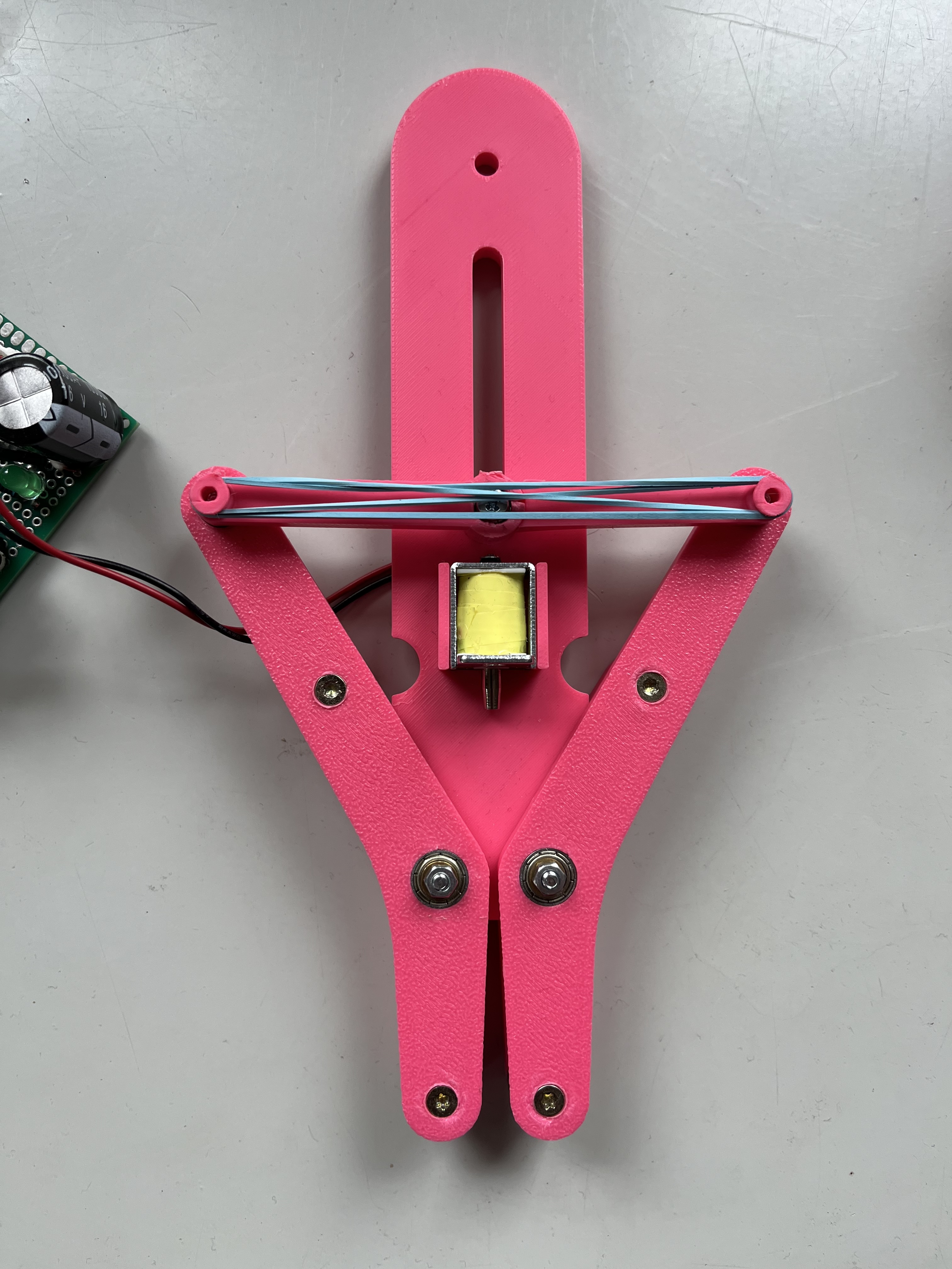
A solenoid needs a very short burst of high current at somewhat higher voltage than electronic circuits. Supplying this is not difficult, just a bit annoying. We can use an electrolytic capacitor charged by a boost converter and controlled via a simple transistor or a MOSFET. The voltages and currents are modest, so we might be able to work with just an NPN transistor.
From the software side, not much changes. Instead of modifying a PWM signal like we need to do for the servo, we just slam a GPIO to high (+3.3V).
The next steps would be to build the hub, try out the integrated system on a nearby hill, and then build a more advanced soft release mechanism.
I already got Spectra fishing line of appropriate strength. The soft release mechanism will be much more complex since it will require an IMU for doing a smooth release.
But I wanted to share the current state.
To be continued...