Lunar Sling Launcher - Tether Dynamics
Whenever somebody proposes a space-based system using tethers, the biggest question is always the dynamic behaviour of the system.
A tether can only be loaded in tension. It has almost no longitudinal passive damping, and lateral damping that is so close to zero that it might as well not exist.

On Earth, you get some damping due to interactions with the air. But in the vacuum of space, a lateral oscillation would remain almost indefinitely.
Tether dynamics has always been the big bogeyman whenever tether-based systems have been proposed.
So let's take a closer look at tether dynamics for a lunar sling launcher.
Masses and springs
To simulate a lunar sling launcher, I have had a LLM write me a simple mass and spring simulation. We use Runge-Kutta for propagation.
A tether is simulated as a chain of masses connected by springs, where the spring rest length, spring constant and mass is chosen to approximate a continuous tether.

To go from a real tether to spring parameters, we split the tether into segments. Each segment contributes a point mass and a spring derived from the material properties of the tether.

For a tapered tether, the cross-sectional area varies along the length, so each segment gets its own distinct mass and spring constant.
The results are qualitative. To actually design a system you would have to do a more fine grained simulation.
But despite just being qualitative, the simulation is very well suited to show the different issues with tether dynamics.
Geometry and tether properties
As a starting point, we are going to use the geometry from the previous post. A radius of 10km and a tip velocity of about lunar escape velocity.
We are going to use the best material that is widely available commercially for use outside the space industry, Dyneema SK99.
The spin up process is interesting for a more detailed design, but since it happens over many hours it isn't very dynamic. So what we are concerned with for now is exclusively the very dynamic release process.
The tip mass must be released with single digit millisecond precision to get precise insertion to EML1.
So let's first configure a system that can spin up to lunar escape velocity and then simulate an instant release.
We will taper the tether so that it is loaded to 75% of ultimate tensile strength everywhere. With SK99 we could afford a larger safety margin, but let's make things exciting.
The simulation
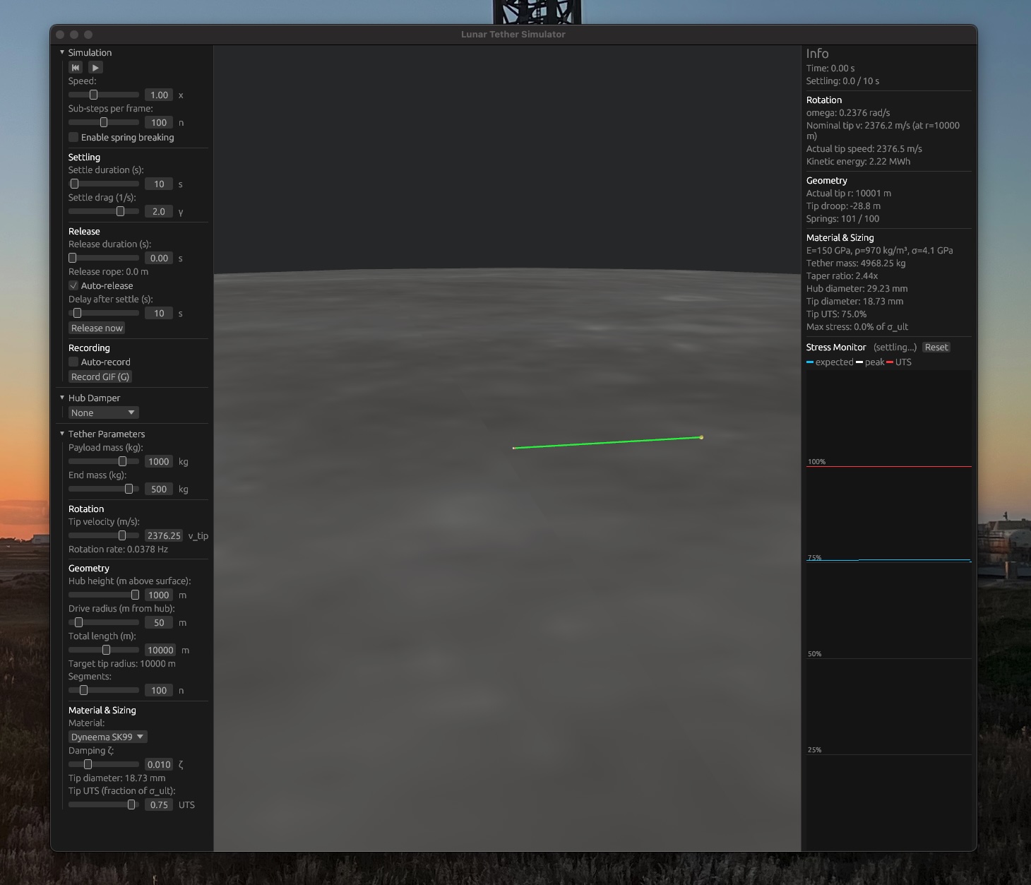
In addition to a config panel that allows configuring tether geometry and material properties, there is an info panel that shows the current state of the simulation: current tip speed, overall kinetic energy and peak stress.
The most interesting display is a plot of the stress on each spring, with the peak stress, expected static stress and the ultimate tensile strength marked.
The simulation will initialize the tether in an unstretched configuration and then allow it to settle for some time with increased longitudinal and lateral damping. Then it will simulate a release by just instantly subtracting the payload mass from the tip mass.
Springs can be configured to break when their UTS is exceeded. So let's do that and see what happens.
Instant release

Peak stress exceeds UTS near the tip
The payload gets released, but a strong longitudinal wave forms and travels towards the hub. It is reflected there and travels back to the tip.
Near the tip, the UTS is locally exceeded and the tether breaks.
So clearly this is not going to work. We could of course drastically oversize the tether, but that would be mass inefficient.
Soft releawse - don't be a jerk
So let's try something different. Instead of instantly releasing the payload, we could let the tip force smoothly decrease until zero by reeling out a bit of extra tether with controlled brake force.

A small reel near the tip holds a length of extra tether. When it's time to release, the reel pays out tether against a controlled brake force. As the extension grows, the centrifugal force on the payload decreases until the extra tether goes slack. Payload release happens exactly when the extra tether is slack.
To get a linear force decrease, the payout length of the release tether must follow
$$l = c \cdot t^3$$

With a soft release duration of 500ms, the tether still breaks, this time near the hub after two reflections.

500ms soft release — stress wave still exceeds UTS
With a soft release duration of 1s, the tether no longer breaks, but there is still very little margin.

Stress stays below UTS but with little margin
With a soft release duration of 1.4s, corresponding to release tether length of 184.5m, we no longer exceed the initial static stress initially.
But after some time the various excited modes constructively combine, and we exceed the initial static stress slightly near the hub.

Stress stays below the initial static stress everywhere
So we have found a way to release without breaking the tether, but there is still a problem. We have strong longitudinal waves traveling along the tether and being reflected on both sides, and even some lateral waves.
The tether has extremely little longitudinal damping and basically zero lateral damping. These oscillations will go on indefinitely until we actively stop them.
Active damping
Active damping can be done simply by reeling out at the hub when the force on the hub is stronger than the expected value, and reeling in when the force is weaker.
Intuitively, reeling out takes energy out of the system at a rate of $$P = F \cdot v$$ where F is the hub tension and v is the reel speed. Reeling in adds power. Since we reel out when force is high and reel in when force is low, net we remove energy from the system.
For reeling out we are limited by the brake force available at the hub, for reeling in by available power to drive the reel motor. For simplicity, let's limit both to around 1000 kW.
With active damping enabled, we see the longitudinal and eventually also the transversal oscillation slowly decrease over a period of a few minutes, until the tether reaches a new equilibrium.
Note that due to the active damping we no longer exceed the initial static stress near the hub!

Oscillations gradually decrease over a few minutes
You might think that active damping would also be an option to reduce the shockwave caused by an instant release. But this is not the case.
Active damping that is strong enough to neutralize the instant release wave would require 10s of megawatts of power, way more than is available in a normally sized reel system.
It is much better to manage this problem with a gradual release. Doing so requires just a reel that can be controlled with a disk brake.
Trying out the sim
The simulation is open source and available on GitHub. It is written in Rust, just like the trajectory sim in the previous blog post and all further code.
But due to the power of coding LLMs you don't need to know Rust to use it. You just need to have a Rust toolchain installed.
git clone https://github.com/rklaehn/tethersim.git
cd tethersim
cargo run --release
You can tweak many sim parameters in the sim gui, and make more complex changes using your favourite coding LLM.
Pre-built binaries are available on the releases page.
Next steps
We have covered the basic concept and available trajectories for a lunar sling launcher in the previous blog post, and problems and solutions for the release dynamics in this blog post.
But there is only so much you can learn with qualitative LLM aided analysis. So the next posts in this series are going to be more practical.
We are going to design, 3d print and test a quick release mechanism with single digit millisecond release precision. We are going to learn how to remote control the mechanism, and eventually build a subscale prototype of a lunar sling launcher.
The only thing that limits us for an Earth based prototype is air resistance. But all complex topics such as release precision and release dynamics can be tested on Earth.
The next part of this series covers the design and testing of a release mechanism.